
Here is a situation we see more often than it should happen: an engineer sends over a CAD file, the design looks clean on screen, and the quote comes back higher than expected or the first article comes back needing a redesign that a ten-minute conversation would have prevented.
Prototyping and CNC milling and machining design decisions made in CAD have direct consequences on the shop floor, and most of the costly ones follow patterns Advanced Precision Machining (APM) has seen hundreds of times across aerospace components, food manufacturing equipment, satellite hardware, and agricultural parts. With over 30 years of hands-on CNC machining experience, we’ve been catching these problems before the first chip flies for decades. These are the seven rules we see most often missed on a first design.
What Is DFM for CNC Machining (And Why It Matters Before You Hit Send)
Design for Manufacturability (DFM) in CNC machining is the practice of reviewing a part design against the physical constraints of cutting tools, fixtures, and machine geometry before any material is touched. The goal isn’t to simplify your design. It’s to make sure the design can be cut accurately, repeatably, and at the cost you intended.
Engineers are trained to design for function, which is correct. But when a design reaches the machine, it has to survive contact with real tooling, real fixturing, and real material behavior. Three things a CAD model can’t account for on its own:
- Tool geometry: A 4-flute end mill can’t cut a perfectly square internal corner regardless of what the stress analysis says.
- Fixturing constraints: A part that can’t be clamped rigidly can’t be cut accurately, no matter how clean the model looks.
- Material behavior: Some materials work-harden under cutting load, deflect under clamping pressure, or respond differently to heat than the spec sheet suggests.
DFM review catches the gap between what works in the model and what works in the cut. At APM, this review happens before a quote is issued. It’s not a premium add-on. It’s how we approach every project, because catching a fixturing problem or an over-specified tolerance in conversation costs nothing, while catching it after a first article costs real money and schedule.
Rule 1: Match Your Tolerances to Function, Not to the Title Block Default
The Most Common and Costly DFM Error
This is the single most common and most expensive DFM mistake we see on first-design drawings. An engineer inherits a title block from a previous project or a company template, carries that tolerance over to a new part, and never asks whether each individual feature actually requires that level of precision.
The result is a drawing where every corner radius, every non-critical face, and every clearance hole is called out to the same tight standard as the mating bore or press fit.
Impact of Tight Tolerances
Spreading tight callouts across an entire drawing adds cost and time on dimensions that could have been cut at general tolerance in a fraction of the time. Specifically, tighter tolerances require:
- Slower feed rates: The tool has less room for error, so cutting speed comes down.
- Additional machining passes: Finishing passes are added to approach the dimension carefully rather than cutting to size in one operation.
- CMM verification time on every controlled feature: Each tight callout becomes an inspection point, and inspection time adds up fast when the whole drawing is toleranced that way.
Practical Application of Tolerances
The practical rule is straightforward: apply tight tolerances to mating bores, press fits, sealing surfaces, and any feature where fit or function genuinely requires it. Use general tolerances everywhere else. Engineers ask us regularly how to achieve a tolerance as inexpensively as possible. This rule is usually the first answer. Our Zeiss CMM is reserved for features that need metrology-grade verification, not applied to every radius on the part.
We take pride in delivering exceptional quality and reliable results, ensuring every part meets exact specifications, on time and on budget. The key word here is exact. We verify what actually needs verifying, not everything on the print.
Rule 2: Design Pockets and Cavities with Tool-Accessible Geometry
Internal Corner Radii
A milling cutter is a cylinder. It can’t cut a perfectly square internal corner. Every inside corner in a pocket will have a radius equal to at least half the diameter of the tool that cut it. Engineers who design pockets with sharp 90-degree internal corners are specifying a feature the machine tooling can’t produce through standard CNC milling.
The fix is simple: add a corner radius to internal pocket corners that matches or exceeds the radius of the tool you expect the shop to use. A slightly larger radius costs nothing in machining time and allows a standard cutter to complete the feature cleanly. A sharp corner requires one of three outcomes, none of them free:
- A secondary EDM operation: Wire EDM adds process time, cost, and a second set of datum handoffs.
- A plunge move that stresses the tool: This increases tool wear and raises the risk of a broken cutter mid-job.
- A reject: If neither option is caught before cutting, the part may not be salvageable.
Depth-to-Width Ratio
Pocket depth matters too. Very deep, narrow pockets require long, thin end mills that deflect under cutting load, producing chatter, poor surface finish, and dimensional drift. As a directional guideline, pocket depth beyond 3 to 4 times the tool diameter adds meaningful machining difficulty. If a deep pocket is genuinely required by the design, the earlier that conversation happens, the better the fixturing and toolpath strategy will be.
Rule 3: Avoid Features That Force Unnecessary Setups
Impact of Multiple Setups
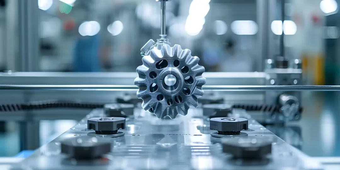
Every time a part is repositioned in the fixture, costs accumulate. A feature machined in the same setup as the rest of the part adds minimal incremental time. A feature that requires its own dedicated setup adds a full cycle of:
- Fixturing: The part must be repositioned and clamped securely for the new orientation.
- Re-indicating: The machine needs to re-establish part datums before cutting can begin.
- Tolerance stack-up risk: Each setup introduces a small positional error. More setups mean more opportunities for those errors to compound.
Consolidating Features
Engineers who place features on five different faces of a part without thinking about whether any of them could be consolidated or slightly reoriented are building setups into the design unnecessarily. In CAD, ask: which features could move to a face already being machined without changing the function of the part?
- Reorient non-critical features: move them to faces already in the machining plan.
- Combine access holes or slots: merge features that serve similar functions into a single feature where geometry allows.
- Flag faces with single isolated features: review before releasing the drawing.
We run multi-axis CNC milling machines that can reduce the number of setups required compared to 3-axis work. Good design still starts with consolidation intent, though, because even the best machine can’t eliminate the cost of a setup that the geometry requires. During DFM review, we flag multi-setup complexity and suggest consolidation options before quoting, so the engineer has a choice rather than a surprise.
Rule 4: Thin Walls and Floors Need a Minimum Thickness You Can Actually Hold
Challenges with Thin Walls
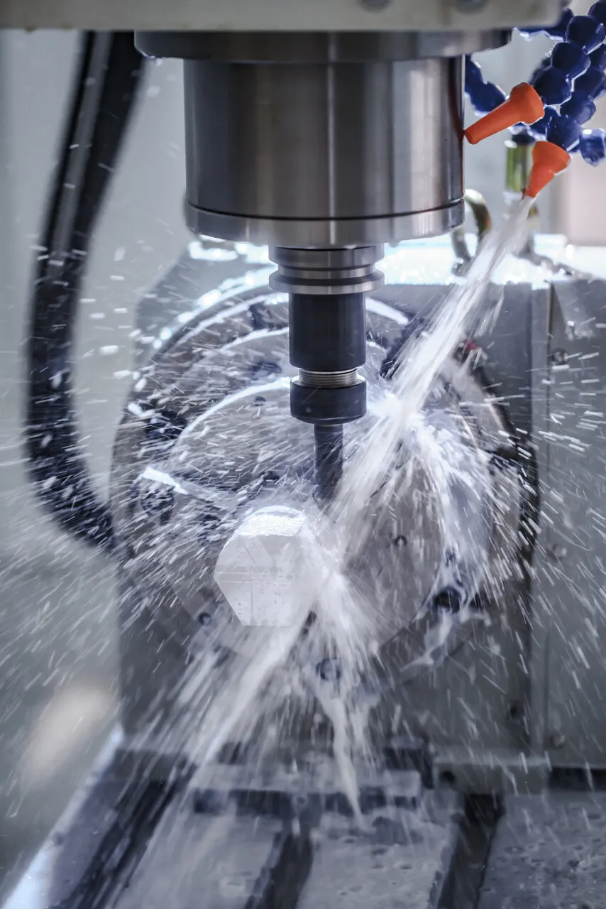
Thin walls flex during machining. Thin floors vibrate. Both produce chatter, poor surface finish, and parts that fail dimensional inspection, not because the programmer made a mistake, but because the geometry doesn’t have enough stiffness to hold still while the tool cuts it.
Engineers optimizing for weight reduction often push wall thickness into a range that creates real problems on the mill. The issue isn’t just nominal thickness. Several factors combine to determine whether a thin section is holdable:
- Height-to-thickness ratio: A wall that’s tall relative to its thickness deflects more under cutting load.
- Clamping location: How the part is fixtured determines where load is transferred and where the wall is unsupported.
- Material stiffness: Aluminum deflects more than steel at the same section thickness. Softer alloys within the same family also vary.
- Tolerance and finish requirements: A tight callout on a thin wall raises the stakes when the wall moves slightly under cutting load.
Planning for Thin-Walled Parts
If thin walls are required by the design, whether for weight in an aerospace component or thermal behavior in a food-processing application, tell the shop before quoting. When thin sections are flagged early, we can plan for:
- Custom fixturing: supports the wall through the cut rather than relying on part stiffness alone.
- Adjusted toolpath sequencing: minimizes lateral load on thin sections during finishing passes.
- Roughing stock management: leaves material in place for rigidity until the final passes remove it.
We have machined thin-walled satellite components and aerospace structures where reduced section thickness is unavoidable. The difference between a difficult job and a failed job is almost always the planning conversation that happened before the first setup.
Rule 5: Threads and Holes Have Preferred Sizes – Use Them
The Cost of Non-Standard Sizes
A non-standard thread size requires a special tap or thread mill. A non-standard bore requires a special reamer or interpolated entry strategy. On a production run, special tooling can be amortized across hundreds of parts. On a single prototype, those costs fall on one part:
- Tooling cost: Special taps, thread mills, and reamers are priced per tool and often not stocked.
- Procurement lead time: A special tool that has to be ordered can add days to a prototype schedule before the first chip flies.
- No fallback if the tool breaks: With standard tooling, a replacement is usually on the shelf. With special tooling, a broken tap can halt the job entirely.
Engineers sometimes design M7 threads or unusual fractional bores because those dimensions worked in a stress model or existed in a CAD library component. Neither of those is a manufacturing reason. If a standard M6 or M8 thread provides the required strength, use the standard size. If a standard drill diameter is within tolerance of the required bore, call it out that way.
Threaded Hole Considerations
For threaded holes specifically, through-holes are preferable to blind holes where function allows it, because blind tapped holes require peck drilling and careful chip management. Hole depth should allow clearance below the thread runout. Our CNC turning team handles threaded cylindrical features routinely and can advise on thread sizing alternatives during DFM review without requiring a change to the part function.
If you aren’t certain whether your geometry requires standard milling operations or a specialized process for a given feature, that’s exactly the kind of question we work through during a pre-quote DFM review.
Rule 6: Sharp Internal Corners Sometimes Need EDM, Not Milling
Sharp internal corners: No standard end mill can cut a truly sharp internal corner. Die cavities, keyways, and certain aerospace structural features are common examples where a square corner serves a real functional purpose, and a milling cutter physically can’t produce a zero-radius internal corner.
When sharp internal geometry is truly required, there are two realistic paths:
- Relief undercut: A small machined clearance allows the corner to appear sharp to the mating component even though the tool left a small radius behind it.
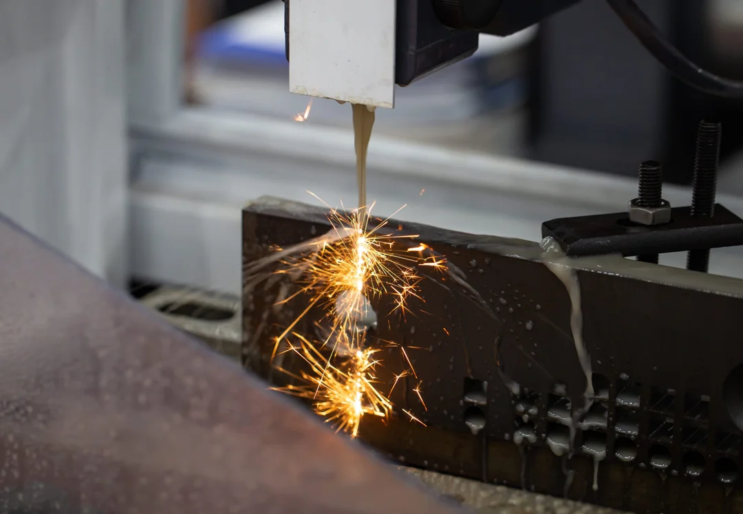
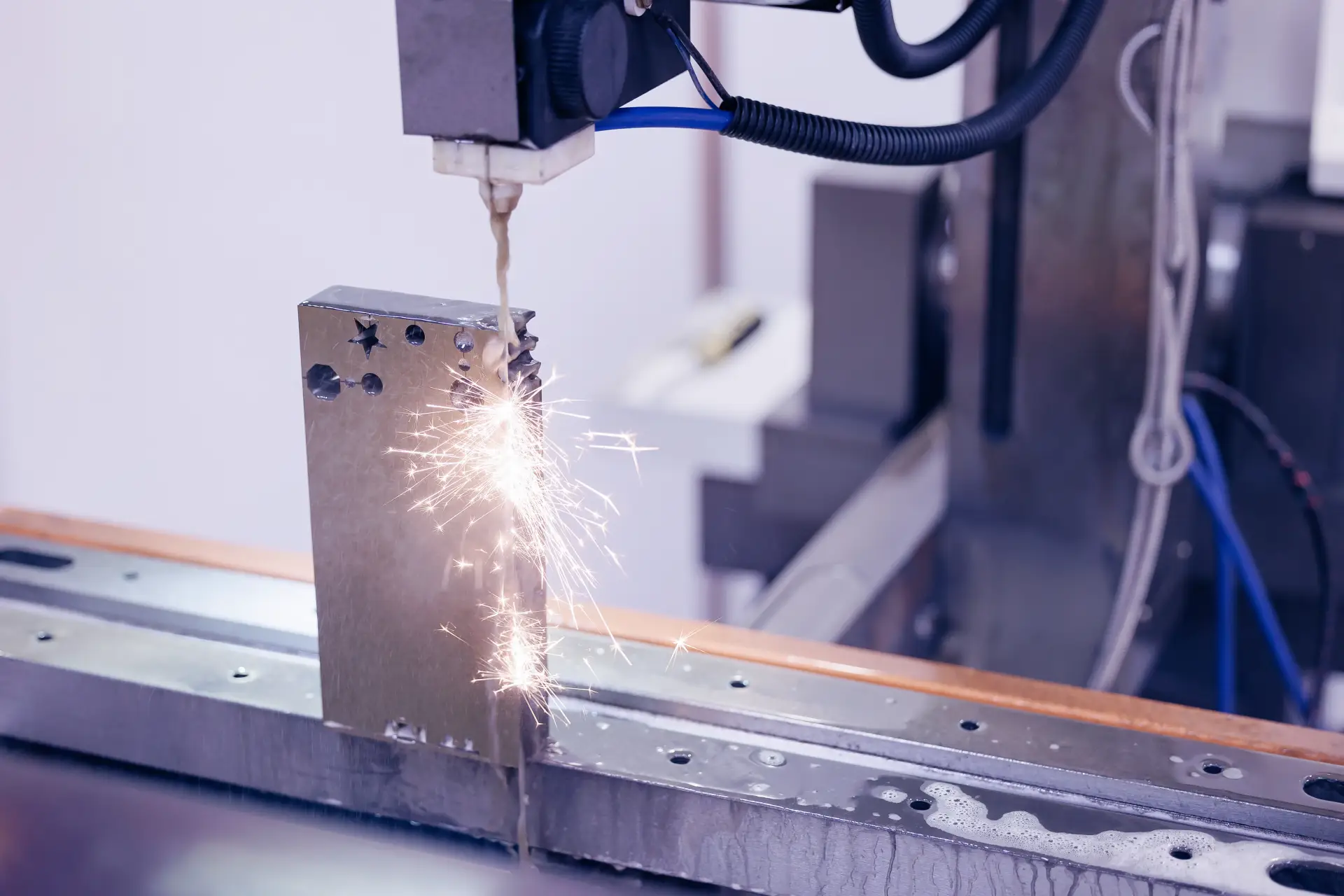
- Wire EDM: Wire EDM cuts with a traveling wire electrode rather than a rotating tool and can produce true sharp internal corners, fine slot geometries, and detailed profiles in hardened materials that milling can’t reach.
Wire EDM isn’t a fallback for a design that couldn’t be milled. It’s the right tool for specific geometry. We operate wire EDM in-house, which means features that require it don’t add a second vendor to the prototype schedule or a second set of datum handoffs to manage.
Rule 7: Material Choice Should Include Machinability, Not Just Mechanical Properties
Machinability vs. Mechanical Properties
Material selection from a stress analysis or a datasheet is the correct starting point for function. It’s not always the complete picture for manufacturing. Machinability varies dramatically between materials that look similar on a spec sheet, and that difference shows up directly in:
- Cycle time: A harder-to-machine alloy requires slower speeds and feeds, which adds time to every operation.
- Tool life: Materials that work-harden or are abrasive wear tooling faster, which raises consumable costs and increases the risk of a tool change mid-job.
- Surface finish quality: Some alloys produce a clean surface at standard parameters. Others require additional finishing passes to meet the same Ra callout.
- Tolerance holding: A material that deflects or springs back under cutting load may be mechanically sound but difficult to hold to a tight dimension on the machine.
Practical Material Examples
A practical example: 304 stainless steel work-hardens aggressively under cutting load and is considerably more difficult to machine than 303 stainless.
For a prototype where corrosion resistance is the requirement but the specific alloy isn’t locked down, 303 is almost always the better first choice. In aluminum, the difference between common aerospace alloys can affect how quickly a prototype comes off the machine, even when both meet the strength requirement.
Early Conversation for Material Selection
The DFM rule here is: when the specification allows a range of acceptable alloys, ask which one machines most efficiently for your geometry and production intent before the drawing is released.
Our team of Colorado CNC machinists works through these decisions routinely across aerospace, food-grade, medical, oil and gas, and agricultural applications. Material selection is one of the places where an early conversation pays off most directly before a part is ever cut.
What a Real DFM Review Looks Like at a Machine Shop
APM’s DFM Process
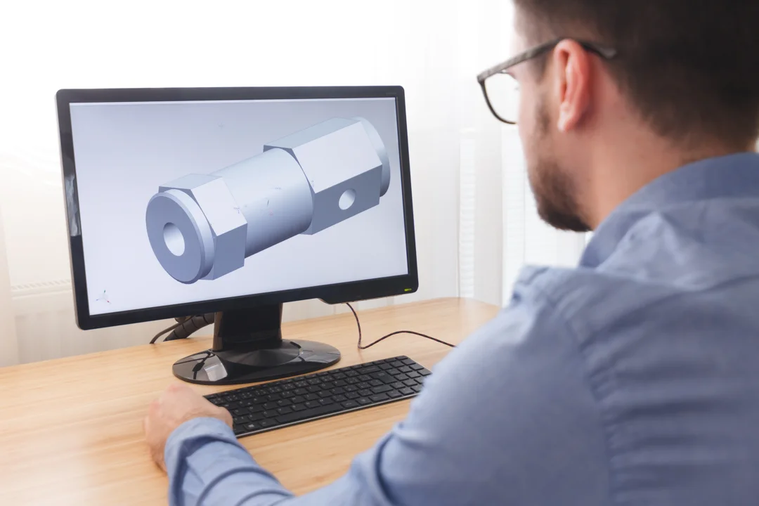
When an engineer submits a CAD file to Advanced Precision Machining, we review the model against the same types of constraints covered in this article before a quote is issued. It’s not a generic checklist email. It’s a direct conversation about:
- Which features are driving cost: and whether the geometry can be adjusted without affecting function.
- Which tolerances can be relaxed: on non-critical features to reduce machining and inspection time.
- Whether any geometry requires special tooling: additional setups, or a process like wire EDM that should be scoped before quoting.
APM as an Engineering Partner
Engineers call us regularly to ask how to achieve a tolerance as inexpensively as possible or to get a better approach to a feature that’s difficult to machine. That’s the standard APM posture, not a consulting add-on. For engineers working on aerospace or defense prototype programs, it also matters that we hold ISO 9001 certification and are ITAR registered, meaning the design data you share with us is handled under the compliance framework those programs require.
DFM and Schedule
When the schedule is tight, we move accordingly. We have turned around rush production orders for food manufacturing customers within roughly one business day when a component failure was threatening to shut down a production line. DFM review doesn’t slow that process down. It makes the first article more likely to be correct when it comes off the machine.
DFM Checklist: 7 Rules at a Glance
Before you send your next CAD file to a machine shop, run through this checklist. Each item maps to a full explanation above.
- Tolerance calibration: Apply tight tolerances only to features where fit, function, or assembly demands it. Use general tolerances on everything else.
- Internal corner radii: Add a radius to every internal pocket corner. A sharp 90-degree internal corner can’t be produced with a standard end mill.
- Pocket depth-to-width ratio: Keep pocket depth within roughly 3 to 4 times the tool diameter to avoid deflection, chatter, and finish problems.
- Setup count: Review the part and consolidate features to as few setups as possible. Each additional setup adds time and tolerance stack-up risk.
- Thin walls and floors: Check wall height-to-thickness ratios, especially in weight-optimized designs. Flag thin sections before quoting so fixturing can be planned.
- Standard threads and holes: Use common thread standards and standard drill sizes. Non-standard tooling adds lead time and cost to a single prototype.
- Material machinability: When the spec allows a range of alloys, ask which one machines most efficiently for your geometry and quantity before the drawing is released.
Frequently Asked Questions About CNC Machining Design and DFM
- What does DFM mean in CNC machining?
- How do tolerances affect CNC prototype cost?
- Can a CNC machine shop redesign my part for better manufacturability?
- What is the difference between prototype machining and production machining?
- When should I use wire EDM instead of CNC milling for internal features?
DFM stands for Design for Manufacturability. In CNC milling and machining, it means reviewing a part design against the physical constraints of cutting tools, fixtures, and machine geometry before any material is cut. The goal is to catch features that will be difficult, slow, or expensive to machine while the part exists only in CAD, when changes cost nothing, rather than after the first article comes back needing rework.
Tighter tolerances require slower feed rates, more machining passes, and CMM verification time on each controlled feature. A part with tight tolerances applied across every dimension costs measurably more and takes longer than the same part with tight tolerances only where function requires them. For prototype machining, engineers should call out the tightest tolerance only on features where fit, assembly, or function genuinely demands that level of precision.
Most machine shops will machine what you send them without comment. APM takes a different approach: before quoting, the team reviews the design and identifies features that drive unnecessary cost or risk, then offers specific suggestions. You retain full control of the design. The shop provides the manufacturing perspective. This is what machine shop prototyping looks like when the shop functions as an engineering partner rather than a quoting portal.
Prototype machining typically involves one to a few parts, with a higher priority on dimensional accuracy and iteration speed than on per-part cycle time. Production machining optimizes for repeatable throughput. DFM rules matter in both contexts, but the prototype stage is where design mistakes are least expensive to catch and fix. Getting DFM right through CNC prototyping services early in a program is how engineers avoid costly engineering changes during production.
Wire EDM is the right process when a design requires true sharp internal corners, very fine slot geometries, or complex profiles in hardened material that a rotating end mill can’t produce. If a part has a keyway, a die cavity, or a through-slot with zero corner radius, EDM is worth discussing before the part goes to the mill.
Get a Free DFM Review Before Your Next Prototype Run
“Our goal is to empower our clients with knowledge.” That’s how we frame every pre-quote conversation, and it’s the same idea behind this article. You now know the seven rules. The next step is applying them to your specific part.
Submit your CAD file to APM for a free DFM review before your next prototype run. We’ll go through the design the same way this article does, covering:
- Tolerances: Which callouts are driving cost and which can be relaxed without affecting function.
- Geometry: Corner radii, pocket depth-to-width ratios, and features that require non-standard tooling.
- Setups: Where consolidation is possible and where a multi-setup approach is unavoidable.
- Wall sections: Thin walls or floors that need fixturing support or toolpath adjustments.
- Material: Whether your alloy choice is the most efficient option for your geometry and quantity.
If something will drive up cost or risk a first-article reject, we’ll tell you before quoting, not after cutting. We’re based in Longmont, Colorado, and serve Front Range customers directly as well as national clients in aerospace, defense, medical device, food processing, oil and gas, and agricultural manufacturing who ship or email files.
Advanced Precision Machining is ISO 9001 certified, ITAR registered, and backed by over 30 years of hands-on CNC machining experience.
Reach out directly at 303-776-1910 to submit your design, or to simply start the conversation. For related resources, visit our prototyping, design, and drafting services page. Our Colorado CNC Milling Guide and our work in aerospace machining details examples of the precision standards we apply to demanding prototype programs.
Advanced Precision Machining
1131 Delaware Ave. #3
Longmont, CO 80501
Phone: 303-776-1910

by Gerry Dillon
Gerry Dillon is a co-founder, current owner and certified CNC machinist at Advanced Precision Machining (APM), a full-service machine shop located in Longmont, Colorado. Gerry has over 30 years of precision milling and machining experience under his belt.