
In optical manufacturing, there’s a principle that experienced engineers understand early and never forget: an optical system can only perform as well as the mechanical structure holding it together. Lens design, coating quality, and material purity all matter, but if the machined components surrounding those optics fail to maintain dimensional integrity at the micron level, system performance degrades. Alignment shifts, beam paths distort, and measurements drift. In high-stakes applications, those consequences aren’t minor inconveniences, they’re program-defining failures.
Micron-level tolerances in optics machining aren’t aspirational specifications reserved for the most demanding programs. They’re functional requirements that directly govern how light travels through a system. Understanding why those tolerances matter, and what happens when they’re not consistently achieved, is essential for optical engineers, OEM product development teams, and procurement professionals who are responsible for sourcing machined components for precision optical assemblies.
This article explains the engineering logic behind tight tolerance optics machining, covers the five primary tolerance categories that govern optical performance, explores the compounding risk of tolerance stack-up, and outlines what to look for when evaluating a precision machining partner like Advanced Precision Machining’s (APM’s) Colorado machine shop for optics applications.
For a broader overview of optics component machining capabilities and industries served, reference APM’s’ Ultimate Guide to Optics Machining Services in Colorado.
Optical Systems Only Perform as Well as the Structures Holding Them
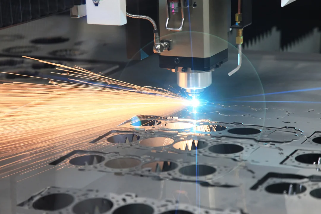
The performance of any optical system, whether it’s an aerospace imaging platform, a medical diagnostic device, a photonics research instrument, or a defense targeting system, is ultimately constrained by the mechanical structures that hold its optical elements in place.
This isn’t a peripheral concern, it’s the central engineering reality of optical system design.
Here’s what that looks like in practice, for example:
- A lens barrel that lacks true concentricity introduces misalignment between optical elements
- A mirror mount with even slight flatness deviation distorts reflected beams
- A structural housing that expands unevenly under thermal load shifts internal geometry and compromises imaging clarity
- An optical bench that deflects under mechanical load changes the spatial relationships between components that were carefully aligned at assembly
In most industrial manufacturing contexts, tolerances provide a reasonable band of acceptable variation. In optics machining, that logic breaks down. Light amplifies mechanical error. A deviation that would be inconsequential in a structural bracket or a fluid fitting can produce measurable, sometimes catastrophic, degradation in optical output. The physics of light propagation, particularly over distance and especially in systems relying on precise beam paths or high-resolution imaging, magnify dimensional errors in ways that are difficult to predict and expensive to correct after assembly.
This is why precision CNC milling and machining for optical components isn’t simply about meeting print dimensions. It’s about understanding how mechanical accuracy produces optical outcomes, and engineering every part of the machining process, including equipment selection, fixturing, thermal management, and inspection, to protect those outcomes consistently.
The Five Tolerance Categories That Define Optics Machining
Optics machining involves a specific set of tolerance categories that are more demanding, and more consequential, than those found in most other precision manufacturing disciplines. Each category connects directly to an optical performance variable. Understanding what each one controls, and what goes wrong when it drifts, is foundational to specifying and sourcing optical components correctly.
1. Concentricity — Keeping Optical Elements on Axis
Concentricity describes how well the center of a cylindrical feature aligns with a reference axis. In optics machining, concentricity control is critical in lens barrels, optical housings, and any assembly that stacks multiple optical elements along a common axis.
What concentricity errors produce:
- Optical centers that shift off the intended axis
- Aberrations and focal inconsistency across the image field
- Beam deviation in collimated optical paths
- Cumulative alignment drift in multi-lens assemblies, where small individual errors compound into significant system-level misalignment
Even tiny eccentricity in a lens housing can alter the relationship between optical elements enough to affect imaging resolution or beam quality. In high-magnification or long-path optical systems, the downstream effect of concentricity error is amplified further. This is why CNC machining for optical housings demands tighter concentricity control than general industrial machining. The tolerance is set by optics physics, not manufacturing convention.
2. Flatness — The Standard for Mirror Mounts and Mating Surfaces
Flatness describes the degree to which a surface lies within a perfectly planar reference. In optics machining, flatness requirements on mirror mounts, optical bench surfaces, and component mating faces are among the most stringent in any manufacturing discipline.
What flatness errors introduce:
- Wavefront distortion in reflected or transmitted beams
- Beam scatter that reduces signal clarity and imaging contrast
- Angular reflection errors that redirect beam paths away from their intended targets
- Mechanical stress on mounted optics during assembly, which can deform sensitive optical elements and alter their performance
Flatness demands increase in applications where beam coherence is critical. Laser systems, aerospace imaging platforms, defense optics, and photonics research equipment all depend on mirror mounts and structural surfaces that maintain near-perfect planarity, not just at assembly, but under the thermal and mechanical loads of actual operation.
3. Perpendicularity — Protecting Optical Axis Stability
Perpendicularity describes the angular relationship between a surface or feature and a reference plane or axis. In optics, perpendicularity errors are particularly consequential because angular deviation at the component level translates into positional error that grows with distance.
A perpendicularity error of a fraction of a degree at the source can translate into a significant positional offset several feet away. That relationship becomes critical in beam delivery systems, long-path laser assemblies, and large-aperture telescope structures.
Applications where perpendicularity is most critical:
- Laser beam delivery and alignment systems
- Telescope and long-path imaging structures
- Beam-shaping and beam-steering assemblies
- Multi-axis imaging devices where angular accuracy governs field-of-view consistency
Tight tolerance CNC milling for optical components must treat perpendicularity as a primary output variable, one that’s actively controlled and measured throughout the machining process, not assumed to fall within spec.
4. Runout — Stability in Rotating Optical Assemblies
Runout measures the variation in a rotating surface relative to a reference axis. In rotating optical assemblies, runout directly determines whether the system can maintain consistent beam positioning, measurement repeatability, and signal quality through each rotation cycle.
What excessive runout introduces:
- Vibration and wobble in the optical path
- Inconsistent beam positioning that varies with rotational position
- Measurement instability in scanning and sensing systems
- Signal noise in photonics and detection applications
Rotating optical systems where runout control is most critical:
- Scanning optics and LIDAR systems
- Rotational imaging assemblies
- High-speed photonics and beam-switching applications
- Polygon mirror systems and optical encoders
Spindle accuracy during CNC milling and machining of rotating optical components is directly connected to system-level measurement reliability. For applications where repeatability is a primary performance requirement, runout tolerances aren’t negotiable.

5. Parallelism — Alignment Across Multi-Optic Assemblies
Parallelism describes the angular relationship between two surfaces or features that are intended to be geometrically parallel. In optical assemblies involving multiple surfaces or stacked optical elements, parallelism errors compound rapidly. Each slightly non-parallel interface adds angular deviation that distorts beam paths between optical surfaces.
Where parallelism errors create the greatest risk:
- Interferometers where fringe pattern accuracy depends on precise surface relationships
- Spectroscopy equipment with multiple dispersive or reflective elements
- Scientific instrumentation requiring consistent beam paths across measurement cycles
- Multi-element imaging systems where surface parallelism governs field uniformity
In precision machining for the optics industry, parallelism control in stacked assemblies requires careful sequencing of machining operations, verified fixturing, and comprehensive final inspection, not just compliance with individual part tolerances in isolation.
When Small Errors Add Up to System Failure: Understanding Tolerance Stack-Up
Individual part accuracy is necessary in optics machining, it’s not sufficient.
One of the most important, and frequently underappreciated, concepts in precision optics manufacturing is tolerance stack-up: the cumulative effect of multiple small dimensional variations combining into a system-level alignment or performance problem.
Here’s how tolerance stack-up typically unfolds in an optical assembly:
- A lens mount is machined to concentricity tolerance. It passes inspection individually.
- A spacer ring is machined to length and perpendicularity tolerance. It passes inspection individually.
- An optical housing is machined to diameter and flatness tolerance. It passes inspection individually.
- A mounting bracket is machined to parallelism and positional tolerance. It passes inspection individually.
Each individual part is within spec. When assembled, however, the cumulative deviation across all four interfaces shifts the optical axis enough to reduce system performance below acceptable thresholds. No single part caused the failure, the assembly did.
The consequences of tolerance stack-up in optical systems include:
- Optical axis alignment that falls outside acceptable bounds at the system level
- Beam instability that can’t be corrected through alignment adjustment alone
- Calibration requirements that increase with operating hours as components settle
- Vibration sensitivity introduced by compounded geometric inconsistency
- Assembly rework that’s expensive, time-consuming, and may require component remanufacture
This is why optics assemblies require holistic dimensional control, not just part-by-part compliance. A machining partner that understands tolerance stack-up will design inspection protocols, establish datum hierarchies, and sequence machining operations with the assembled system in mind, not just the individual component drawing.
In optics manufacturing, cumulative error matters more than isolated error.
Can parts that pass individual inspection still cause optical system failure?
Yes, this is the tolerance stack-up problem. Components that each meet their individual dimensional specifications can combine in assembly to produce cumulative deviation that pushes system-level alignment or beam accuracy outside acceptable bounds. It’s one of the most common and costly sources of optical system failure, and it’s why holistic dimensional control across an entire assembly matters as much as part-level inspection compliance.
For more detail on the tolerance expectations APM maintains for optical component machining, visit the Optics Machining Guide tolerance section.
What Happens When Tolerances Aren’t Met: Real-World Consequences
The consequences of tolerance failure in optics machining aren’t abstract, they translate directly into engineering problems, schedule disruptions, and business risk for the programs and organizations involved.
Across APM’s primary optics end markets, tolerance failures produce outcomes like these:
- Aerospace imaging systems lose targeting or mapping accuracy when mechanical misalignment shifts the optical axis beyond correction range, requiring field recalibration or component replacement in environments where access is limited or impossible
- Medical diagnostic devices produce inconsistent readings when optical alignment drifts, introducing measurement variability that affects diagnostic reliability and regulatory compliance
- Laser systems experience beam instability, power loss, or unintended beam steering when housing or mount tolerances allow optical elements to shift from their designed positions
- Research instrumentation requires increasingly frequent recalibration when dimensional instability in machined components allows alignment to drift over time, reducing throughput and introducing measurement uncertainty
- Defense optics fail environmental qualification testing when thermal cycling or vibration loading reveals that machined components can’t maintain alignment within the required tolerance band under operating conditions
The downstream business consequences of these failures include:
- Redesign costs and engineering hours spent diagnosing root cause
- Failed validation cycles that delay product launch or program milestones
- Warranty exposure and field reliability liability
- Rework and scrap costs when out-of-tolerance components must be remanufactured
- Reputational risk with end customers in industries where system reliability is a primary purchasing criterion
Precision machining at the micron level is, from the buyer’s perspective, a form of risk mitigation. The cost of sourcing from a machining partner with documented tight-tolerance capability is consistently lower than the cost of recovering from a tolerance failure in a fielded optical system.
For industries where these stakes are highest, reference APM’s Aerospace Machining Guide, Medical CNC Machining Guide, or our Scientific Instrument Machining Guide.
Precision Is More Than CNC Accuracy — Material Behavior Matters Too
Achieving and maintaining micron-level tolerances in optics machining isn’t solely a function of machine tool capability. Material selection and behavior play an equally important role in whether a machined optical component retains its dimensional accuracy through the full lifecycle of assembly, environmental exposure, and operational use.
Key material factors that affect optical component stability:
- Thermal expansion: When interfacing components in an optical assembly have mismatched coefficients of thermal expansion (CTE), alignment shifts under temperature variation. Material pairing in optical assemblies requires careful engineering consideration, not just individual material selection
- Stress relief: Residual machining stress can cause slow dimensional change after parts leave the machine. Proper stress relief protocols, whether through thermal treatment, aging, or machining strategy, are essential for maintaining long-term dimensional stability
- Vibration damping: In dynamic optical environments, a material’s ability to absorb rather than transmit vibration affects how well an assembly maintains alignment under operational loads
- Environmental resistance: Humidity, chemical exposure, and pressure variation can affect the dimensional stability of certain materials over time, particularly in field-deployed optical systems
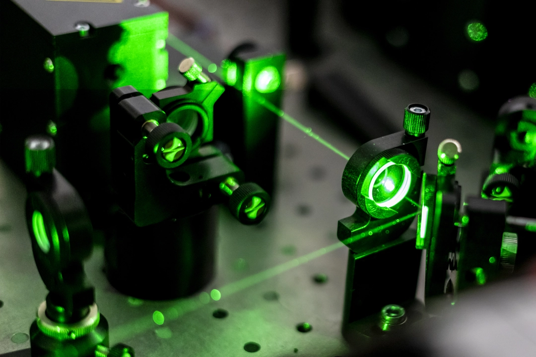
Common material choices in precision optics machining and why they’re selected:
- Aluminum alloys: Lightweight, thermally manageable, and highly machinable; widely used in optical housings, benches, and structural frames
- Stainless steel: High rigidity and corrosion resistance for demanding environments
- Titanium: Exceptional strength-to-weight ratio for aerospace and medical optics applications
- Invar and low-expansion alloys: Selected specifically for thermal stability in systems where CTE mismatch must be minimized
- Engineering polymers (PEEK, Ultem, Delrin): Used in specialized photonics and sensing applications where weight, electrical properties, or chemical resistance are priorities
A precision machining partner with genuine optics experience will bring material knowledge into the conversation at the design stage, not just execute on a specified material after the engineering decision has already been made.
You Can’t Achieve Micron Precision Without Micron-Level Measurement
Precision optics machining and precision inspection are inseparable disciplines. A machine shop that claims micron-level tolerance capability without equally capable measurement systems isn’t delivering verified precision. It’s making an unsubstantiated claim.
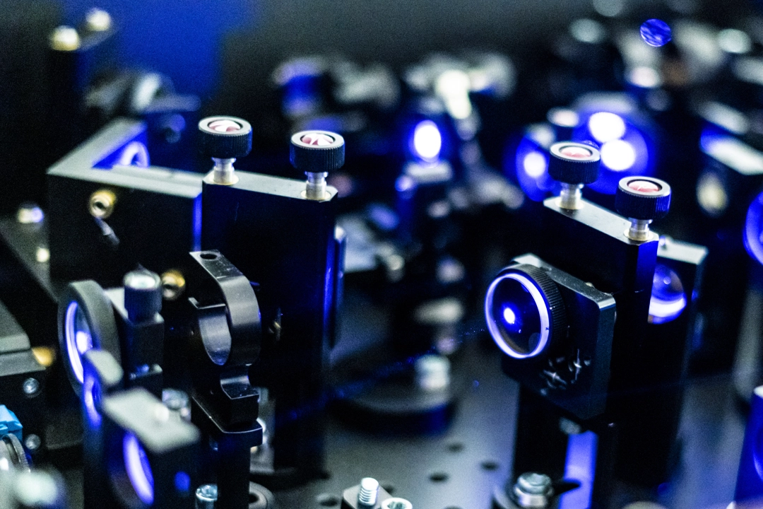
Inspection methods relevant to tight-tolerance optics machining include:
- Coordinate Measuring Machine (CMM) inspection: Provides three-dimensional verification of geometric relationships including concentricity, perpendicularity, flatness, parallelism, and positional accuracy
- Surface measurement and profilometry: Characterizes surface finish and flatness to a level of detail that supports optical performance prediction
- Optical comparators: Enable rapid visual verification of part geometry against reference profiles
- In-process verification: Inspection performed during machining, not only at final inspection, allows dimensional drift to be caught and corrected before it propagates through a part or a production run
- Calibration traceability: Measurement equipment calibrated to national standards provides the documentation trail that aerospace, medical, and defense programs require for compliance
Why documented inspection matters for optical buyers:
- It provides objective evidence that parts meet performance-critical specifications, not just a machinist’s judgment
- It creates a traceability record that supports validation, qualification, and regulatory compliance requirements
- It catches tolerance stack-up risks at the component level before assembly reveals them
- It gives engineering teams the data they need to make informed decisions about fit, form, and function at the system level
At Advanced Precision Machining, tolerance validation is treated as a core deliverable, not an afterthought. Learn more about APM’sInspection Reporting capabilities.
Not Every Machine Shop Can Hold Micron-Level Tolerances in Optics Applications
Many machine shops are capable of producing accurate parts. Significantly fewer have the process discipline, equipment capability, inspection infrastructure, and domain knowledge required to consistently achieve and verify micron-level tolerances in optical component machining, across production volumes, across material types, and across the environmental conditions those parts will eventually face.
What separates a precision optics machining partner from a generalist shop:
- Process control and thermal management: Micron-level machining requires controlled environments. Temperature variation in a machine shop affects both the machine tool and the workpiece. Shops producing tight-tolerance optics components manage these variables deliberately, not incidentally
- Advanced metrology infrastructure: CMM capability, surface measurement equipment, and calibrated inspection systems are prerequisites, not optional add-ons, for optics machining work
- Material knowledge specific to optical applications: Understanding how aluminum, titanium, Invar, and engineering polymers behave during and after machining, and how to sequence operations to preserve dimensional stability, requires experience that generalist shops often lack
- Demonstrated repeatability: Holding a tolerance once on a prototype is a different capability than holding it consistently across a production run. Optics programs require repeatable precision, not one-time precision
- Engineering collaboration: The best outcomes in optics machining come from early engagement between the machining partner and the optical engineering team. Design for manufacturability conversations, tolerance stack-up analysis, and material pairing recommendations all have a meaningful impact on final system performance
Choosing a machining partner with specific optics experience isn’t a procurement preference. It’s an engineering decision that affects the reliability, schedule, and cost of the entire optical program.
For full details on Advanced Precision Machining’s optics machining capabilities, services, and industries served, please visit our Optics Machining Guide. To discuss a specific project, contact the Advanced Precision Machining team directly.
Frequently Asked Questions: Micron-Level Tolerances in Optics Machining
- What are micron-level tolerances in optics machining and why do they matter?
- How does tolerance stack-up affect optical system performance?
- What tolerance categories are most critical in precision optics machining?
- What materials are commonly used in precision optics machining and how does material choice affect performance?
- How do I evaluate whether a machine shop is qualified to produce precision optical components?
Micron-level tolerances refer to dimensional accuracy requirements measured in micrometers, where one micrometer equals one-thousandth of a millimeter. They matter because optical systems amplify mechanical error through the physics of light propagation. A deviation of just a few microns in a lens housing, mirror mount, or optical bench can degrade beam stability, imaging resolution, and alignment accuracy in ways that can’t be corrected after assembly. In optics machining, micron-level tolerances aren’t a quality preference. They’re a functional requirement.
Tolerance stack-up occurs when multiple components, each individually within spec, combine in an assembly to produce cumulative dimensional deviation that the system can’t accommodate. In optical assemblies, small variations across lens mounts, spacers, housings, and brackets can accumulate enough to shift the optical axis, destabilize beam paths, or push imaging accuracy below acceptable thresholds. This is why parts can pass individual inspection and still cause system-level failure. A qualified optics machining partner accounts for stack-up risk throughout the entire machining and inspection process, not just at the part level.
The five tolerance categories that most directly govern optical performance are:
- Concentricity: Controls whether optical elements stay centered on a common axis. Critical in lens barrels and multi-element housings.
- Flatness: Governs the planarity of mirror mounts and mating surfaces. Directly affects wavefront quality and beam reflection accuracy.
- Perpendicularity: Small angular errors at the component level produce large positional errors over distance.
- Runout: Excessive runout in rotating assemblies introduces vibration, beam wobble, and measurement inconsistency.
- Parallelism: Errors compound across stacked optical interfaces and distort beam paths in multi-element assemblies.
Material selection directly affects dimensional stability, thermal behavior, and long-term alignment reliability. Common choices include:
- Aluminum alloys: Lightweight and machinable. Widely used in housings, frames, and optical benches.
- Stainless steel: High rigidity and corrosion resistance for demanding environments.
- Titanium: High strength-to-weight ratio for aerospace and medical optics applications.
- Invar and low-expansion alloys: Selected when thermal expansion mismatch between interfacing components must be minimized.
- Engineering polymers (PEEK, Ultem, Delrin): Used where weight, electrical properties, or chemical resistance drive the specification.
Material pairing between interfacing components matters as much as individual material selection. When mating parts expand at different rates under temperature change, alignment shifts even if both parts were perfectly machined to spec.
Look for these five indicators:
- Metrology infrastructure: CMM inspection capability, surface measurement tools, and calibration traceability. Claimed tolerances without documented measurement are unverified.
- Process and environmental control: Ask how the shop manages temperature variation, fixturing consistency, and in-process dimensional verification.
- Material experience: The shop should understand how optical assembly materials behave during and after machining, including stress relief and stabilization protocols.
- Tolerance stack-up awareness: A qualified partner designs inspection and machining processes around how parts perform together in assembly, not just individually.
- Relevant industry experience: Look for demonstrated experience in aerospace, medical, defense, or scientific instrumentation, where documentation requirements and tolerance demands are highest.
Micron-Level Tolerances Are the Difference Between Optical Systems That Perform and Those That Don’t
The through-line is straightforward: In optics manufacturing, mechanical precision isn’t a supporting discipline. It’s a performance variable. Every micron of dimensional deviation in a machined optical component is a potential source of beam instability, alignment drift, imaging degradation, or system failure.
The five tolerance categories that govern optics machining, concentricity, flatness, perpendicularity, runout, and parallelism, each connect directly to optical outcomes. Tolerance stack-up explains why part-level compliance is necessary but not sufficient. Real-world failure consequences illustrate why the cost of precision is almost always lower than the cost of imprecision. Material stability and environmental factors demonstrate that precision machining is a holistic discipline, not just a function of machine tool accuracy. And inspection capability determines whether any of it can be verified and trusted.
Successful optics machining programs share four characteristics:
- Advanced CNC machining capability with process control designed for micron-level tolerances
- Rigorous inspection and documented metrology that validates, not just claims, dimensional accuracy
- Material knowledge and engineering collaboration that accounts for how parts behave in the real world, not just on a drawing
- A machining partner experienced enough to understand how mechanical precision affects optical performance, and to take responsibility for protecting it
Advanced Precision Machining brings all four to every optics program we support. If you’re developing or sourcing precision machined components for an optical system, we’d welcome the opportunity to discuss your requirements.

by Gerry Dillon
Gerry Dillon is a co-founder, current owner and certified CNC machinist at Advanced Precision Machining (APM), a full-service machine shop located in Longmont, Colorado. Gerry has over 30 years of precision milling and machining experience under his belt.